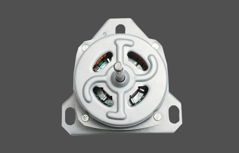
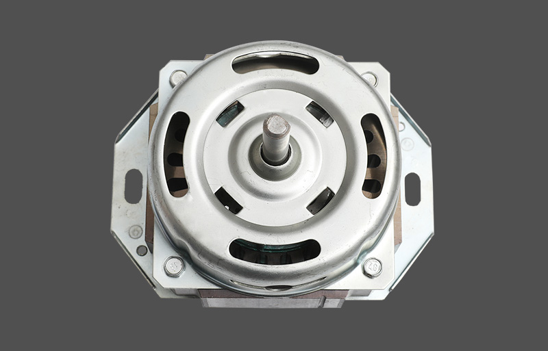
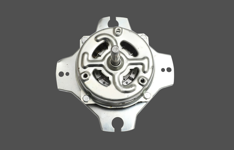
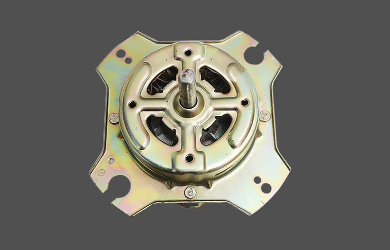
In modern air conditioning systems, fan motors play a central role. They must not only provide stable airflow but also ensure long-term, efficient, and reliable operation. To achieve this, fan motors and their drive circuits are designed with sophisticated "triple protection": overcurrent protection, overvoltage protection, and overtemperature protection. These protection mechanisms act as the motor's "guardians," rapidly responding to abnormal operating conditions to prevent damage or even more serious accidents.
Overcurrent Protection: Stopping Current "Floods"
Overcurrent protection is one of the most common protection measures for fan motors, designed to prevent motor burnout due to excessive current. Abnormal current increases can occur for a variety of reasons, such as fan blades becoming stuck, bearings becoming stuck, drive circuit shorts, or excessive voltage fluctuations. When current exceeds the motor's rated value, significant Joule heating is generated, rapidly increasing coil temperature, ultimately leading to insulation failure or even burnout.
Overcurrent protection can be implemented in several ways:
Hardware current sensing: This is the most direct and reliable method. Engineers typically connect a current-sensing resistor (such as a shunt resistor or Hall effect sensor) in series with the drive circuit to monitor the current flowing through the motor in real time. When the voltage across the resistor exceeds a preset threshold, the driver chip (MCU/DSP) detects an overcurrent event and immediately cuts off power to the motor. This method offers fast response and is the core of the protection circuit.
Software Current Limiting: In PWM (Pulse Width Modulation)-controlled fan motor drivers, current limiting can be achieved through a software algorithm. The driver chip continuously samples the current. When the current approaches a dangerous level, the MCU proactively reduces the PWM duty cycle, thereby reducing the output voltage and current, keeping the current within a safe range. This method provides more precise protection and prevents transient current surges.
Fuses: Using a resettable condenser fuse (PPTC) or a disposable fuse at the power input is a simple and effective overcurrent protection method. When the current exceeds a certain level, the PPTC's resistance increases dramatically, limiting the current; a disposable fuse, on the other hand, melts, completely disconnecting the circuit. While simple, this method does not automatically recover and requires manual replacement.
Overvoltage Protection: Protects against voltage spikes
Overvoltage protection primarily addresses abnormally high power supply voltages. For example, grid fluctuations, lightning strikes, or power module failures can all cause transient voltage spikes. Excessive voltage can breakdown driver chips (such as MOSFETs) and capacitors, and in severe cases, can cause circuit board fires.
Overvoltage protection methods include:
TVS (Transient Voltage Suppressor) diodes: Connecting a TVS (Transient Voltage Suppressor) diode in parallel with the power supply input is a common protection measure. A TVS diode exhibits high resistance under normal voltage. When the voltage momentarily exceeds its clamping voltage, it quickly conducts, diverting excess energy to ground, thereby clamping the voltage to a safe level and protecting subsequent circuits.
Varistor: Varistors operate on a similar principle to TVS diodes, but have a slower response speed and greater energy absorption capacity. They are typically used to absorb high-energy voltage surges and protect circuits from damage.
Software protection: The ADC (analog-to-digital converter) built into the driver chip monitors the power supply voltage in real time. When the voltage exceeds a safe threshold, the software executes overvoltage protection procedures, such as stopping the driver output and entering fault protection mode until the voltage returns to normal.
Overheat Protection: Protecting Against High-Temperature Corrosion
Fan motors will continue to heat up when operating under high load for extended periods or when heat dissipation is poor. High temperatures are detrimental to electronic components and motor coils, causing insulation degradation, magnetic demagnetization, and bearing lubrication failure, ultimately leading to permanent damage to the motor. Overheat protection is crucial for ensuring long-term motor reliability.
Overheat protection is implemented primarily through the following methods:
Thermistors (NTC/PTC): Installing NTC (negative temperature coefficient) or PTC (positive temperature coefficient) thermistors on motor windings or driver heat sinks is a common practice. NTC resistance decreases with increasing temperature, while PTC resistance decreases. By monitoring the change in thermistor resistance, the MCU can accurately determine the motor temperature. When the temperature exceeds a preset safety threshold, the controller initiates a protective procedure, such as reducing motor speed to reduce heat or directly shutting off the power supply.
Internal Chip Temperature Sensor: Some high-end driver chips or MCUs have integrated temperature sensors. These built-in sensors monitor the chip's temperature in real time. When the chip overheats, they automatically reduce operating frequency or shut down output to prevent burnout. External temperature sensor: For high-power motors, an independent temperature sensor (such as a thermocouple) is often installed on the motor housing to more accurately monitor the overall motor temperature and provide feedback to the main control system. If the temperature exceeds the specified limit, the air conditioning system will make appropriate adjustments, such as issuing an alarm or shutting down the unit.


