


An Air Cooler Fan Motor does one job that decides whether an evaporative cooler feels refreshing or disappointing: it moves a steady volume of air across a wet cooling pad and pushes the chilled airstream into the room. Blade shape, pad thickness and water flow all matter, but none of them can compensate for a motor that runs slowly, overheats or hums. Two questions come up again and again among people who own or service these machines: which motor is used in an air cooler, and how do I know if my AC fan motor is bad. This page answers both, and adds the specifications, test values, maintenance intervals and production details that help you judge a motor properly.
Most evaporative coolers use a single-phase AC induction motor with a permanent split capacitor (PSC). Compact desktop units often use a shaded pole motor, premium quiet units use a brushless DC (BLDC) motor, and large industrial units use a three-phase induction motor.
Typical signs are a fan that will not start, a fan that spins slowly, grinding or humming noises, a hot motor casing, a burnt smell and tripping protection. A multimeter check of the capacitor, winding resistance and insulation confirms the cause.
Humid air, mineral dust from evaporated water, long daily running hours and frequent speed changes. Good insulation, sealed or well-lubricated bearings and a correctly rated capacitor are the three features that decide service life.
An evaporative cooler is a simple machine on the outside and a carefully balanced system on the inside. A pump lifts water from the tank and distributes it over the cooling pad. The Air Cooler Fan Motor turns the blade or blower wheel, which pulls warm room air through the damp pad. As water evaporates it absorbs heat, so the air leaving the cooler is cooler and carries more moisture. The motor sits behind or beside the pad, often only a short distance from the water path, which is why its insulation and enclosure design matter far more than they do in a dry-air fan.
The motor is also the main electrical load in the cooler. The pump usually draws less than twenty watts, while the fan motor may draw anywhere from twenty-five watts in a small tabletop model to more than two kilowatts in a large industrial cabinet. Because airflow rises roughly in proportion to speed while power input rises much faster, the way the motor is wound and controlled has a direct effect on running cost, noise and comfort.
Mains voltage passes through the speed selector and the running capacitor into the main and auxiliary windings.
The capacitor shifts the current phase in the auxiliary winding, creating the rotating magnetic field that starts and holds the rotor in motion.
The blade draws room air through the pad, where water evaporation removes heat from the airstream.
The blower or axial blade pushes the cooled airflow through the louvers and into the room at the selected speed.
There is no single motor that suits every cooler. The correct choice depends on cooler size, expected running hours, noise targets and the control features the cooler offers. The four designs below cover almost every Air Cooler Fan Motor in use today.
This is the most common answer to the question of which motor is used in an air cooler. A permanent run capacitor remains connected to the auxiliary winding at all times, which gives smooth torque, low vibration and a stable running speed. Speed is normally changed through winding taps, so a three-speed or four-speed selector switch is enough to control it. The design is simple, tolerant of voltage variation and easy to repair, which suits floor-standing and tower coolers for homes and shops.
Typical range: 60 W to 250 W
A copper ring around part of each stator pole produces a weak rotating field without any capacitor. The result is a compact, inexpensive motor with low starting torque and modest efficiency. It works well for small personal coolers where the blade is light and airflow demand is low, but it generates more heat per watt of shaft output and is not recommended for long, continuous running in large units.
Typical range: 15 W to 60 W
A permanent-magnet rotor and an electronic controller replace the capacitor and tap switch. Speed can be changed in small steps or continuously, power consumption is low at reduced speed, and the motor runs quietly. The controller adds electronic components that must be protected from moisture, so enclosure quality and board coating are important design points. These motors suit quiet bedroom coolers and remote-controlled units.
Typical range: 30 W to 200 W
Large industrial and commercial coolers moving tens of thousands of cubic meters of air per hour use three-phase power. These motors deliver strong, constant torque, handle belt-driven blowers and run well under heavy duty. Speed is adjusted with a variable frequency drive, and thermal protection is usually built into the windings.
Typical range: 370 W to 2.2 kW
| Motor Type | Starting Torque | Speed Control | Noise Level | Best Suited For |
|---|---|---|---|---|
| Shaded pole | Low | Tap switch, limited steps | Medium | Small desktop coolers |
| PSC single-phase | Medium | Tap switch, 3 to 4 speeds | Low to medium | Home and shop coolers |
| BLDC | High | Electronic, stepless | Very low | Quiet and remote-controlled coolers |
| Three-phase induction | High | Variable frequency drive | Medium to high | Workshops, warehouses, halls |
Running cost is easier to understand when power input is plotted against fan speed. The chart below compares a PSC induction motor with a BLDC motor driving the same blade. Both deliver comparable airflow at each speed, but the BLDC design draws noticeably less power, and the gap widens as speed falls. The difference is most obvious on long summer evenings, when a cooler runs for many hours at low or medium speed.
Values are representative of a 150 W-class Air Cooler Fan Motor driving the same blade and are intended for comparison between designs, not as a guarantee for any single model.
Mid-point of typical efficiency ranges at rated load.
The nameplate on an Air Cooler Fan Motor contains most of what you need to confirm compatibility or judge quality. Reading it correctly avoids the common mistake of matching only power and ignoring speed, rotation direction or mounting dimensions, all of which affect airflow and noise.
| Specification | What It Tells You | Common Values |
|---|---|---|
| Rated voltage and frequency | Supply the motor was wound for | 110 V, 220 V to 240 V, 50 Hz or 60 Hz |
| Rated power | Shaft output at full load | 25 W to 2.2 kW depending on cooler size |
| Rated speed | Rotor speed under load | 800 to 1400 RPM for most coolers |
| Capacitor rating | Microfarad value and voltage of the run capacitor | 2 to 12 µF, 400 V to 450 V |
| Insulation class | Maximum winding temperature | Class B (130 °C) or Class F (155 °C) |
| Protection rating | Resistance to water and dust | IP20 to IP44 for most designs |
| Rotation direction | Clockwise or counter-clockwise seen from shaft end | Must match blade pitch |
| Shaft diameter and length | Fit with the blade or blower hub | 6 mm to 12 mm for common sizes |
| Duty type | Continuous or short-time operation | S1 continuous duty preferred |
Insulation class deserves special attention in a humid cooler. Class F insulation allows a higher temperature rise before the varnish starts to age, which gives the motor extra margin when the room is hot and the cooler runs all day. A motor that survives only because it never runs close to its limit will lose that margin quickly once dust or scale builds up.
Winding quality is the largest single factor behind motor life. Copper-wound stators carry current with lower loss than aluminum windings and run cooler for the same output, so they keep their insulation in better condition across years of use. The enamel coating on the wire, the slot insulation paper and the varnish impregnation all form a layered barrier against moisture. A vacuum impregnation process fills the tiny gaps between turns, locks the wire in place so it cannot vibrate against its neighbor and gives heat a path to the stator core.
The stator core is stacked from thin silicon steel laminations. Thinner laminations and a tighter stack reduce eddy-current losses and magnetic noise. A well-built Air Cooler Fan Motor also uses a die-cast aluminum rotor that has been dynamically balanced, because even a small imbalance becomes a rhythmic vibration once it is mounted in a thin plastic or sheet-metal cooler body.
Lower resistance, lower heat and a longer insulation life under continuous running.
Fills gaps between turns, resists moisture entry and prevents wire movement under vibration.
A small thermal cut-out inside the winding opens the circuit when the temperature climbs beyond a safe limit.
The bearing system carries the weight of the rotor and the radial load of the blade. In coolers it is also the part that suffers most from dust, scale and lack of lubrication. Two designs dominate the market, and each has a clear place.
| Feature | Oil-Impregnated Sleeve Bearing | Ball Bearing |
|---|---|---|
| Running noise | Very low when fresh and lubricated | Slightly higher, stable over time |
| Tolerance to missing lubricant | Low, wear rises quickly | Higher, grease is sealed in |
| Mounting orientation | Best with horizontal shaft | Any orientation |
| Typical service life | Shorter in dusty rooms | Longer under heavy duty |
| Cost | Lower | Higher |
For a cooler that runs many hours each day in a dusty environment, a ball bearing Air Cooler Fan Motor offers greater margin. For a bedroom cooler where silence matters most and the unit is cleaned regularly, an oil-impregnated sleeve bearing can serve very well.
A failing motor rarely stops without warning. In most cases the cooler gives hints for days or weeks before the final breakdown. Learning to recognize them lets you replace a capacitor or bearing early instead of losing the whole motor. The following signs are the most reliable answers to the question of how do I know if my AC fan motor is bad.
If the motor hums but the blade does not turn, the run capacitor has most likely lost its capacity or the bearings have seized. Turn the blade gently by hand with the power off. If it spins freely and the motor starts after a push, the capacitor is the prime suspect.
A weak airflow at the same selector position points to capacitor drift, increased bearing friction, a shorted turn in the winding or low supply voltage. Compare the current speed with the high-speed value on the nameplate.
Dry bearings produce a high-pitched squeal. Worn bearings produce a rough grinding sound. A rhythmic rattle often comes from a loose blade hub or a bent blade rather than from the motor itself.
If you cannot keep your hand on the casing for several seconds after thirty minutes of operation, the winding is carrying too much current or the cooling path is blocked by dust.
Overheated varnish produces a sharp, sweet and acrid smell. Switch off and unplug the cooler immediately. The winding insulation has already started to fail.
A fan that stops and restarts by itself often indicates a thermal protector that is repeatedly opening. A tripped breaker may indicate leakage from the winding to the motor body.
| Symptom | Most Likely Cause | First Check |
|---|---|---|
| Hums, no rotation | Failed run capacitor or seized bearing | Measure capacitance, turn blade by hand |
| Slow speed on all settings | Capacitor drift or bearing friction | Measure capacitance and shaft resistance |
| Slow speed on one setting only | Open or shorted tap in winding | Measure resistance of each tap |
| Loud scraping noise | Worn bearing or blade touching housing | Check shaft play and blade clearance |
| Hot casing | Overload, dust blockage or winding fault | Clean vents, measure running current |
| Breaker trips | Winding leakage to body | Measure insulation resistance |
| Burnt smell | Insulation breakdown | Stop use, replace motor |
A basic digital multimeter and a clamp meter are enough to test an Air Cooler Fan Motor properly. Always disconnect the cooler from the mains and discharge the capacitor before touching any terminal.
Look for discolored casing, melted insulation on lead wires, swollen capacitor bodies, rust on terminals and scale deposits around the shaft.
Turn the blade by hand. It should coast smoothly for a second or two without roughness. Any catching or axial wobble suggests a bearing problem.
Measure with the capacitance range of a meter. A reading more than ten percent below the printed value indicates it should be replaced.
Measure the main winding, auxiliary winding and each speed tap. Compare with the specification or with a known good motor of the same model.
Measure between each winding lead and the motor body. A value below 2 megohms signals moisture or insulation damage.
Measure operating current with a clamp meter and compare it with the nameplate. Check the casing temperature after thirty minutes.
| Test | Healthy Reading | Faulty Reading |
|---|---|---|
| Run capacitor | Within 10% of printed value | More than 10% low, bulged case or zero |
| Main and auxiliary winding | Stable resistance close to specification | Infinite (open) or near zero (shorted) |
| Tap-to-tap resistance | Resistance changes progressively by speed | One tap far out of pattern |
| Winding to body insulation | 2 megohms or higher | Below 2 megohms |
| Running current | At or below nameplate value | Clearly above nameplate value |
| Casing temperature after 30 minutes | Warm, comfortable to touch briefly | Too hot to hold |
The run capacitor controls torque, speed and temperature. A capacitor with too little capacity gives weak starting torque and a slow, hot motor. One with too much capacity pushes extra current through the auxiliary winding and also overheats the motor. Always match microfarad value, voltage rating and physical size to the original specification.
| Motor Power | Typical Capacitor Value | Voltage Rating |
|---|---|---|
| Up to 40 W | 1 to 2 µF | 400 V |
| 60 W to 100 W | 2 to 4 µF | 400 V to 450 V |
| 120 W to 180 W | 4 to 6 µF | 450 V |
| 200 W to 250 W | 6 to 10 µF | 450 V |
Temperature rise during the first hour of running separates a healthy Air Cooler Fan Motor from a failing one. A healthy motor climbs quickly during the first minutes, then flattens and holds a stable value. A motor with a weak capacitor or worn bearings keeps climbing without leveling off. The chart below shows the pattern.
Illustrative curves for comparison. Absolute values depend on room temperature, cooler design and motor rating.
Service records for evaporative coolers show a consistent pattern. A handful of root causes account for nearly all motor failures, and most of them are connected to moisture, dust and electrical stress rather than to the original design. The chart gives an illustrative breakdown.
Capacitors fail more often than any other component because they are small, hot and work continuously. Bearings follow closely, since lubricant dries out with heat and scale dust works its way into the shaft area. Winding failures tend to be a consequence of earlier problems: an overheated motor with a weak capacitor or a worn bearing stresses the insulation until it fails.
Moisture deserves its own mention. Water vapor enters the motor with every breath of air it moves. If the motor housing has open vents directly facing the pad, droplets and fine mineral particles can settle on the winding and slowly create leakage paths. A cooler designed with the motor shielded behind a baffle or a splash guard extends motor life significantly.
Most motor failures can be pushed years into the future with a short seasonal routine. The table below sets out a practical schedule. None of the tasks require specialist tools.
| Interval | Task | Reason |
|---|---|---|
| Every week in use | Wipe blade and grille, check for unusual noise | Dust adds load and imbalance |
| Every month in use | Drain and clean the tank, remove scale from the pump area | Scale spray can reach the motor |
| Start of each season | Inspect cord, plug and terminals, turn blade by hand | Finds loose contacts and tight bearings early |
| Start of each season | Apply a few drops of light machine oil to serviceable sleeve bearings | Restores lubrication lost during storage |
| End of each season | Dry the cooler fully, store in a dry and ventilated place | Prevents moisture damage to windings |
| Every two seasons | Measure capacitor value and winding insulation | Detects hidden ageing before breakdown |
Let the pump run for a few minutes before switching the fan to high speed so the pad is wet and the airflow resistance is stable. Avoid running the cooler with an empty tank, because the dry pad restricts airflow differently and changes the load. Keep the cooler at least a short distance away from walls and curtains so the intake is never blocked.
Not every symptom justifies a new motor. A capacitor replacement costs very little and restores a surprising number of cooler fans that appeared to be dead. A bearing replacement is reasonable when the shaft and housing are undamaged. Winding faults are different: once insulation has broken down, the repair rarely lasts, and the safer option is a new Air Cooler Fan Motor.
The capacitor has drifted but the windings test normally. The bearings are noisy but the shaft is straight and the housing bore is not worn. A terminal or lead wire is loose or corroded. The blade is dirty or slightly unbalanced and the motor itself tests well.
The winding is open, shorted or leaking to the body. The shaft is bent or has axial play that cannot be removed. The insulation smells burnt or shows dark discoloration. The motor still fails to start after fitting a new capacitor.
When choosing a replacement, match voltage, frequency, power, speed, rotation direction, shaft size, mounting hole spacing and lead wire length to the original. A motor that is nominally the same power but rotates the opposite way will move much less air, even though it seems to run perfectly.
Airflow capacity, tank size and cooling area form a set. A motor that is too small cannot pull enough air through the pad, and the cooler delivers warm and damp air. A motor that is too large wastes electricity, makes noise and may blow droplets past the pad. The table gives representative combinations for common cooler classes.
| Cooler Class | Tank Capacity | Airflow Target | Typical Motor |
|---|---|---|---|
| Personal desktop | 2 to 5 L | 200 to 400 m³/h | Shaded pole, 15 W to 35 W |
| Bedroom tower | 8 to 20 L | 500 to 1000 m³/h | PSC or BLDC, 40 W to 90 W |
| Living room floor unit | 30 to 60 L | 1500 to 3500 m³/h | PSC or BLDC, 100 W to 200 W |
| Shop and small workshop | 60 to 100 L | 4000 to 8000 m³/h | PSC, 180 W to 370 W |
| Large industrial cabinet | Plumbed supply | 10,000 to 40,000 m³/h | Three-phase, 750 W to 2.2 kW |
As a factory that produces motors in our own workshops, we follow a fixed production path from raw material inspection to final packing. Each stage has measurable limits, and every finished Air Cooler Fan Motor is tested before it leaves the line. The stages below show how the motor you receive is built.
Enamelled copper wire, silicon steel laminations, bearings and varnish are checked for dimensions, insulation strength and cleanliness before entering production.
Automatic winding machines keep turn counts and tension consistent. Slot insulation is inserted and coils are shaped to avoid wire damage.
Stators are impregnated with varnish under vacuum and then cured, sealing gaps and improving heat transfer and moisture resistance.
Die-cast rotors are balanced dynamically so that the motor runs smoothly once the blade is fitted.
Bearings are fitted with controlled press force and lubricated with the specified grease or oil quantity.
Each unit is run on a test bench to confirm current, speed, power, noise and temperature rise against the specification.
| Factory Test Item | What Is Verified |
|---|---|
| No-load and full-load current | Current stays within the specified tolerance at every speed tap |
| Speed measurement | Rotor speed matches the design value at each setting |
| High-voltage insulation test | No breakdown between windings and the motor body |
| Insulation resistance | Resistance stays above the required minimum |
| Noise measurement | Sound level stays within the limit for the motor class |
| Temperature rise | Winding temperature stays within the insulation class limit |
| Rotation direction | Direction is checked and marked against the order specification |
| Vibration | Rotor balance is confirmed on the test stand |
Coolers differ in housing shape, blade diameter, intake area and control system, so a motor that fits one design may not suit another. Our engineering team adapts the Air Cooler Fan Motor to the cooler rather than asking the cooler design to adapt to the motor. The following options can be set at the production stage.
Voltage from 100 V to 277 V, frequency of 50 Hz or 60 Hz, and the number of speed taps from two to five.
Shaft diameter, shaft length, flat or keyway cut, mounting bracket style, hole spacing and overall body length.
Clockwise or counter-clockwise rotation, matched to blade pitch for maximum airflow and low noise.
Class B or Class F insulation, thermal protector fitted inside the winding, and moisture-resistant varnish treatment.
Oil-impregnated sleeve bearings for quiet service, or ball bearings for long continuous running.
Lead wire length, color coding, connector type and capacitor attached or supplied separately.
A correct installation protects the motor as much as a correct selection. Begin with the power disconnected and the water tank empty. Photograph the wiring before removing any lead, since tap colors differ between designs. Remove the blade, noting the position of the set screw on the shaft flat. Slide the old motor out, clean the mounting surface and compare the new motor against the old one for shaft height and bracket position.
When the new motor is in place, fasten the mounting hardware evenly so the housing is not distorted. Tighten the blade set screw onto the shaft flat and confirm that the blade turns without touching the housing or grille. Connect the leads according to the photograph, secure them away from the water path and ensure the capacitor is clamped, not left hanging on its leads. Finish with a free rotation test and a short run at low speed before running at full speed.
Blade clearance all around, no wire touching the shaft or housing, capacitor firmly clamped, earth connection in place, and no water path directed at the motor vents. A cooler passing these checks is ready for normal use.
The majority of household and shop coolers use a single-phase PSC induction motor. Small desktop coolers often use a shaded pole motor, quiet and remote-controlled coolers use BLDC motors, and large industrial coolers use three-phase induction motors. The choice follows airflow demand, noise target and control features.
Watch for a fan that fails to start or turns slowly, grinding or humming noises, a hot casing, burning smells and repeated tripping. Confirm with a multimeter by measuring capacitor value, winding resistance and insulation resistance, and with a clamp meter by comparing running current with the nameplate.
Yes. A weak run capacitor leaves the motor without enough starting torque, so it hums and does not turn. If the blade spins freely by hand and the motor then starts, the capacitor is the likely cause and replacing it often restores normal running.
Common reasons are a drifted capacitor, extra bearing friction, a shorted turn in the winding, a worn selector switch or low supply voltage. Measuring the capacitor and checking the shaft by hand will identify most of these.
A warm casing is normal. A casing too hot to hold, accompanied by a burnt smell or repeated stopping, points to overload or insulation damage. Switch the cooler off and have the motor tested before using it again.
Service life depends on insulation class, bearing type, running hours and environment. With clean air, correct voltage and seasonal maintenance, a quality motor with copper windings can serve for many seasons. Dust, scale and humidity shorten that life.
It is possible only when the cooler is designed for it. A BLDC motor needs an electronic controller and a different speed selector, so a direct swap into a tap-controlled cooler is not practical without changing the control circuit.
The blade will still turn, but it pushes much less air and often produces more noise. Rotation direction must match the blade pitch, so confirm it before fitting a replacement motor.
Indirectly. Scale, spray and splashed droplets can reach the motor and create leakage paths in the winding or corrosion in the bearing area. Cleaning the tank regularly and keeping the motor shielded from splashes reduces that risk.
Class F gives a higher temperature margin than Class B and suits coolers that run long hours in hot rooms. Class B is suitable for lighter duty when the motor has plenty of cooling airflow.
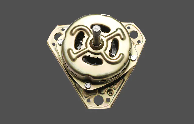
Ty001 Double-Tub Washing Machine Dedicated Motor
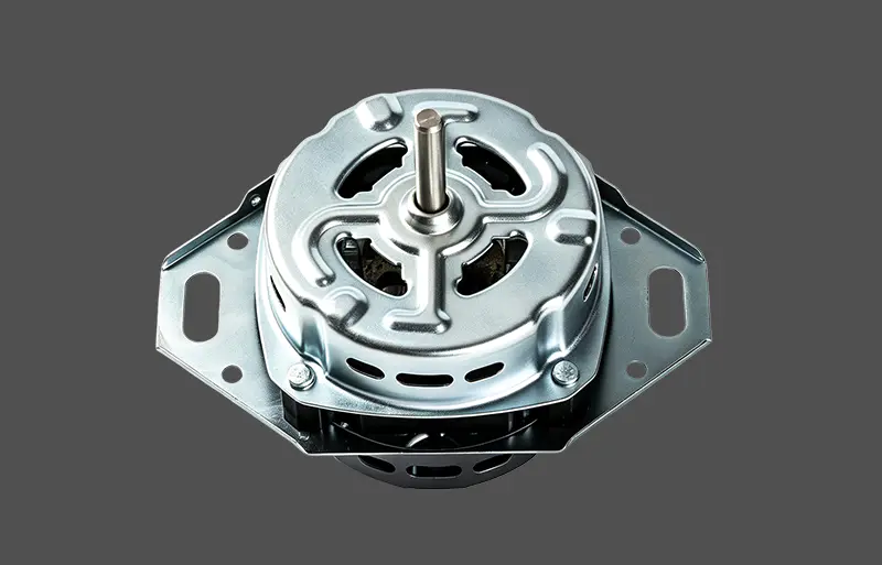
TY002 Powerful & Durable Copper-Wound Washing Machine Motor
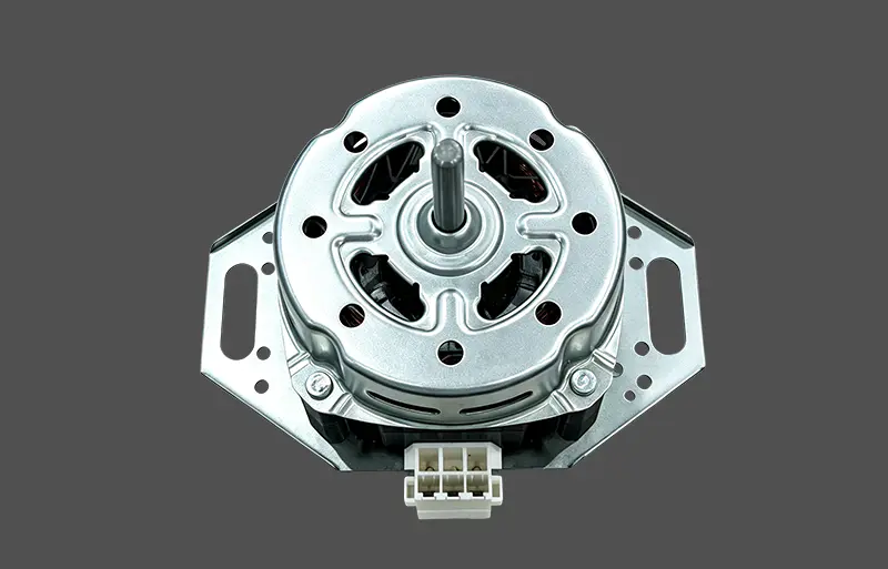
Environmental Cover Washing Machine Motor
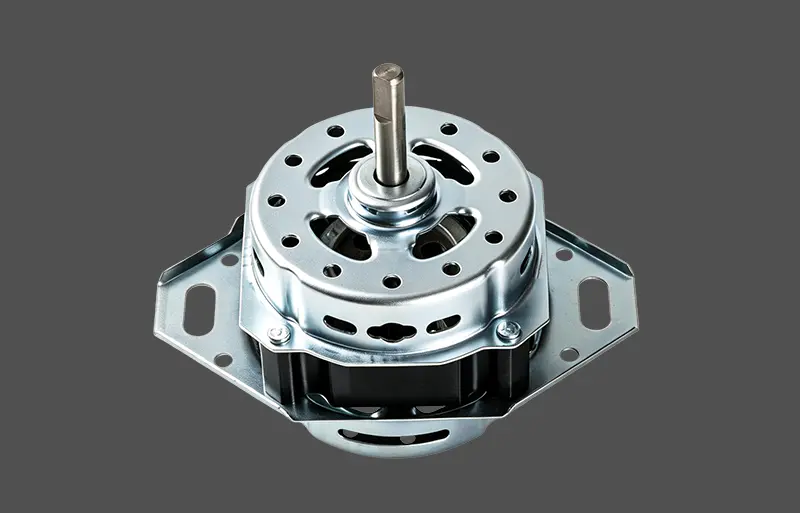
TY004 High-Efficiency Mini Copper Wire Washing Machine Motor
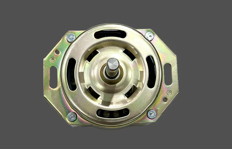
TY005 100% Copper Wire High-Speed Induction Motor
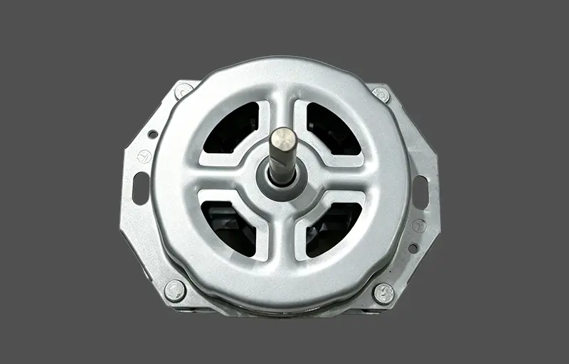
Home Appliance Parts Washing Motor
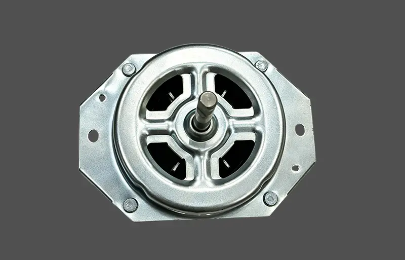
White Color CCA Motor
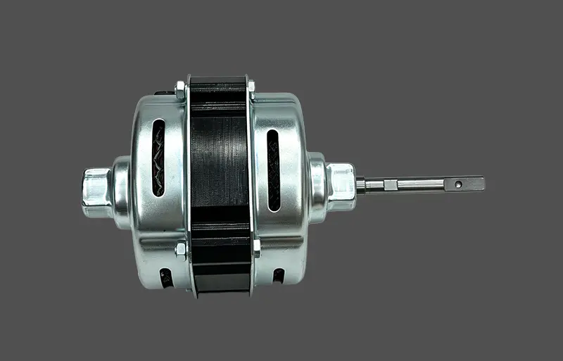
TY-008
Please leave your Email or phone nomber, so we can contact you as soon as possible.
Share


